2030 Ic 2.1 Amplifier Circuit Diagram
What is the TDA2030? TDA2030 is a monolithic integrated circuit in Pentawatt package, intended for use as a low frequency class AB amplifier. It provides 14W output power (d = 0.5%) at 14V/4Ω at ± 14V or 28V, the guaranteed output power is 12W on a 4Ω load or 8W on a 8Ω

TDA 40W 2030 IC ඇම්පිලීෆයරය
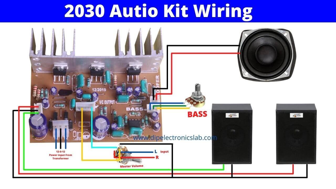
TDA2030 home Theater circuit diagram 4.1 Home theater Kit wiring Diagram Tda2030 Home Theater kit Connection According to the above picture, I will explain to you the connection of TDA2030 Amplifier kin in any sound system, such as 2.1 Home theater, 4.1 Home theater, etc. First Step: Power Supply Connection

Tda2030 Ic Circuit Diagram
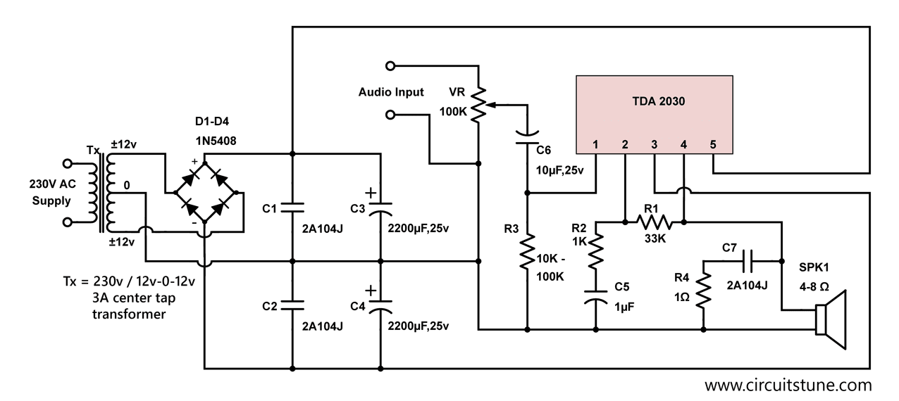
The external components you need for this TDA2030 amplifier circuit diagram are as follow: TDA2030 IC (1) Resistor 22KΩ (2) 390Ω (1) 100Ω (1) 2.2Ω (1) Capacitors 22µF (1) 10µF (1) 100nF - 104 (3) Others Speaker and -12 GND +12V dual rail power supply; The circuit should be mounted on an efficient heat sink to absorb the heat from the IC.

2030 Ic Subwoofer Circuit Diagram
TDA2030 Single IC Full Circuit Diagram Making Amplifier Simple & Powerful RJ EDIT ALL 286K subscribers Join Subscribe 2.6K Save 162K views 2 years ago TDA2030 Single IC Full Circuit Diagram.
Home Theatre Circuit Board Diagram Wiring View and Schematics Diagram
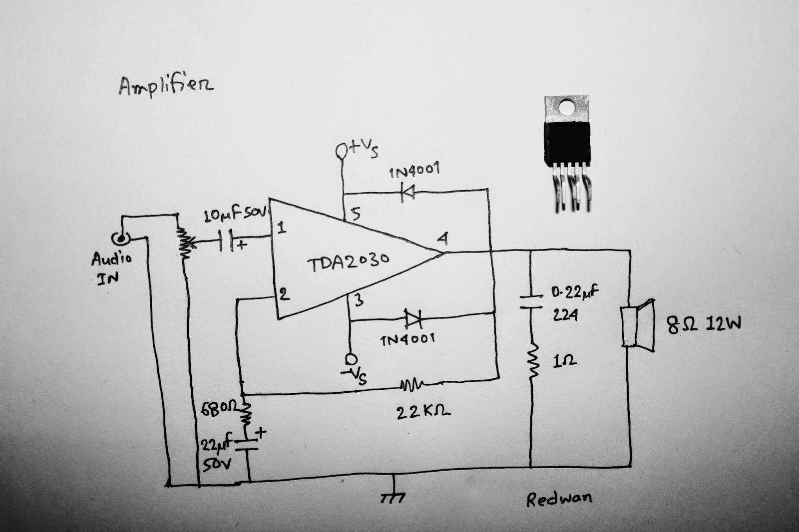
Ask Question I Made It! TDA2030 Amplifier Circuit 12v : The maximum voltage with standing by the TDA2030 amplifier is 36v, this is the reason why many changes are needed to build a 12v TDA2030 amplifier.
Circuit Power Amplifier Ic Tda With Pcb W Rms SexiezPicz Web Porn
797 Share 26K views 3 months ago #hometheatre #tda2030ic #tda2030ic #hometheatre #2030iccircuitdiagram how to make tda 2030 ic circuit diagram. how to make circuit of 2030 ic. home.

Elsie Circuit 2030 Ic Audio Board Circuit Diagram
Tessie 15 September 2021 14529 60mA mA 140 kHz kHz 18W W Audio Amplifiers 20W W 5 pins Pentawatt-5 (Vertical, Bent and Staggered Leads) TDA2030 is a 14w hi-fi audio amplifier. This article mainly covers pinout, datasheet, applications, alternatives, and more details about TDA2030.

2030 Ic Audio Board Circuit Diagram Wiring Diagram Schematic
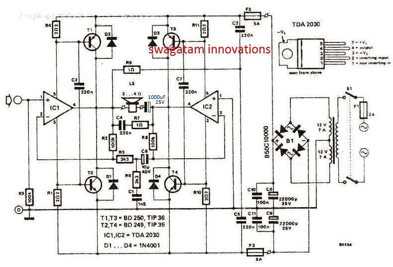
Circuit diagram of 35 watts Bridge Amplifier using TDA2030 However, you can get more 35W output on TDA2030 in a bridged connection with a +- 15V power supply. In the circuit above, there are two TDA2030 that are connected together. Both the output terminals—Pin 4 connect to the speaker. You can learn the bridge amplifier works here.
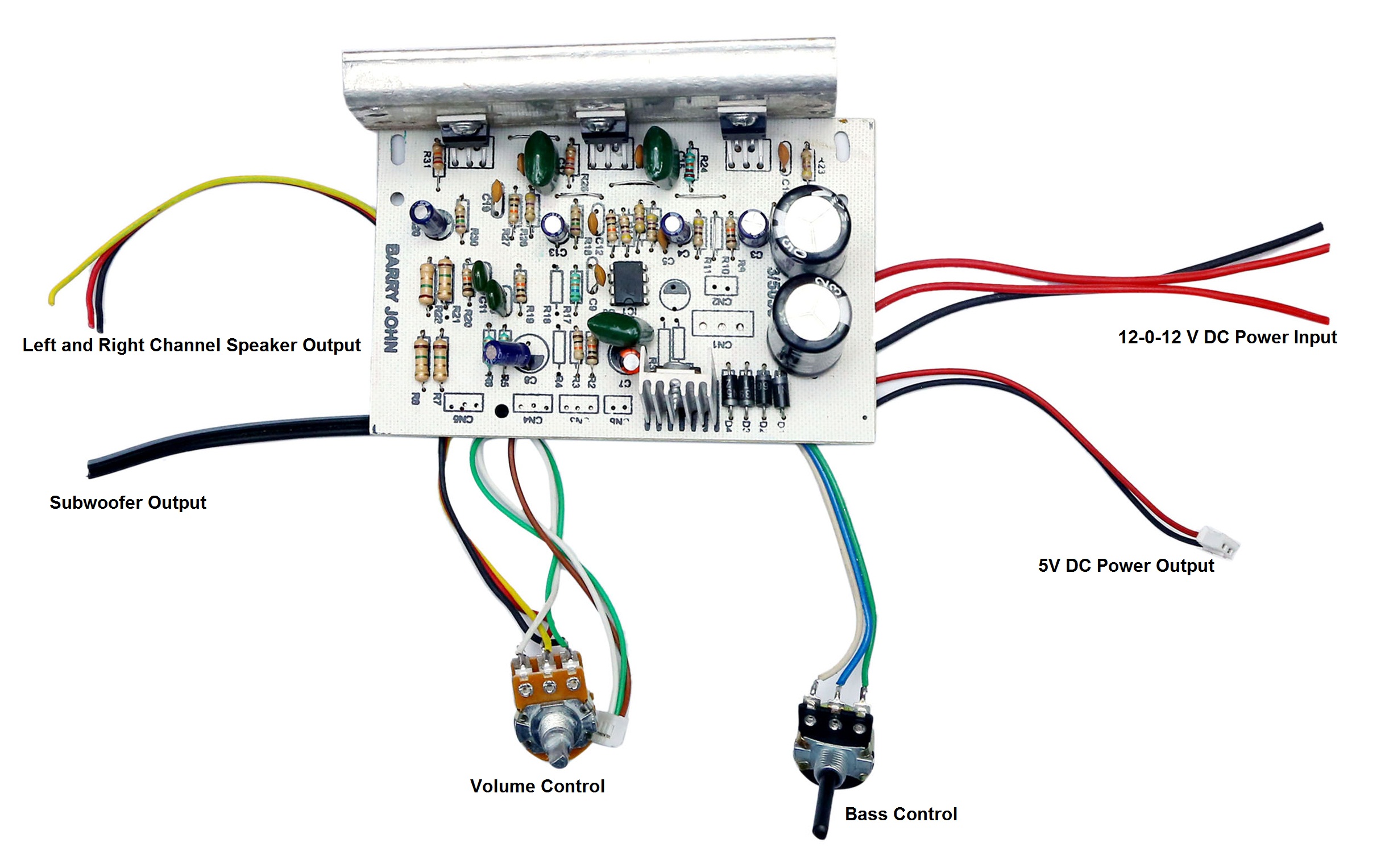
Buy Barry John 2030 IC Home Theater 2.1/4.1/5.1 Sub Woofer Amplifier Board With Bluetooth Module
The amplifier circuit diagram using the TDA2030 IC is an excellent choice for those looking to build an audio amplifier with a high output power. The TDA2030 IC's ability to deliver up to 20 watts of continuous output power makes it suitable for driving larger speakers with ease.

4.1 Home Theater Wiring Diagram ItIsworth
TDA2030 IC - 1 Resistors - 100K (3), 4.7 K (1), 10 ohm (1) Capacitor - 100 mf (1), 0.1 mf (2), 2.2 mf (2) , 22mf (1) Diode - In4007 (1) Speaker (1) Battery - 12 V (I used SMPS) 22k variable resistor-1 (To adjust volume if needed) Features and Pin Detail of TDA2030 Amplifier:

2030 Ic Audio Board Circuit Diagram
TDA2030 Product details. The TDA2030 is a monolithic integrated circuit in the Pentawatt package, intended for use as a low frequency class-AB amplifier. Typically it provides 14 W output power (d = 0.5%) at 14 V/4 Ω. At ±14 V or 28 V, the guaranteed output power is 12 W on a 4 Ωload and 8 W on an 8 Ω (DIN45500).
2030 Ic Subwoofer Circuit Diagram
The TDA2030 IC is a powerful audio amplifier IC able to deliver up to 20W of output power, so you can use it to run a 4Ω speaker at 12W or a 8Ω speaker at 8W. TDA2030A Pinout Configuration Features · Low frequency class AB amplifier most suited for audio amplification · Can provide up to 20 Watts as output power
2030 Ic Home Theater Circuit Diagram Wiring View and Schematics Diagram
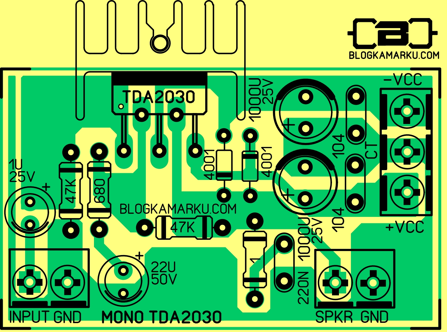
TDA2030 amplifier circuit board diagram. TDA2030 is a circuit integrated monolithic in Pentawat® package, to be used as class audio amplifier AB. Typically, he supplies up to 14 Watts of potency (d=0.5%) @ 14V/4 Ω. The guaranteed potency is 12W in a load of 4 Ω and 8 watts in a load of 8 Ω. Integrated him/it bills with circuits of component.
Scavenger's Blog 10W Mono Amplifier With TDA 2030
2030 ic amplifier circuit diagram | TDA2030 | TDA2030 Single IC Amplifier Full Circuit Diagram Hi I am ARNAB GIRI. Welcome to Our YouTube Channel Tech Warm T.
Transistor amplifier 120
Steps to Build the TDA2030 Amplifier Circuit. Place the TDA2030 IC on the heat sink and solder it in place. Connect a 100nF ceramic capacitor and a 100uF /25V capacitor between pin 5 and the ground of the TDA2030 IC. Connect a 47KΩ resistor between pin 1 and the ground of the audio input jack. Place a 1.5KΩ resistor and a 1uF capacitor in.

2030 Ic 4.1 Amplifier Circuit Diagram скачать Zoya Circuit
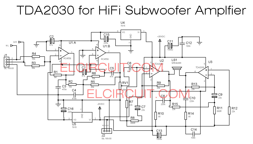
The circuit is divided into 3 parts: power supply, stereo amplifier and bass amplifier (subwoofer). TDA2030 2.1 amplifier board circuit diagram subwoofer. This circuit is a complete application is 2.1 amp, two satellite speakers for TDA2030 and one for the subwoofer, the 2.1 system, widely used in commercial applications as an amplifier for.